
Several modeling tools are available for elements in building models:
- Vertical line
- Column
- Wall
- Beam
- Rectangular floor
- Polygonal floor
- Rectangular floor opening
- Polygonal floor opening
This feature allows you to define the element on the ground plane (for example, with a background layer) with the associated multiple element creation in space.

- The results of the connection design can be entered in the printout report
- When creating a new printout report, select the items added from the Steel Joints Add-on
- Use the tool 'Print Graphics to Printout Report' to insert graphics with the results of the connection, including the control panel, into the report
- Printout report contains the specifications of the connection components, design parameters, results and graphics
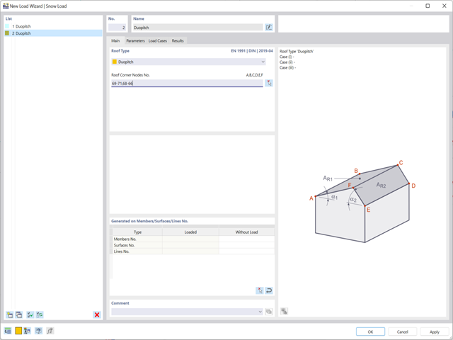
Discover the new functions of the snow and wind load wizards:
- Loading of hybrid models made of members and surfaces (RFEM only)
- Connection to the Geo-Zone Tool (depending on the global construction site definition)
- Switching off surface sides
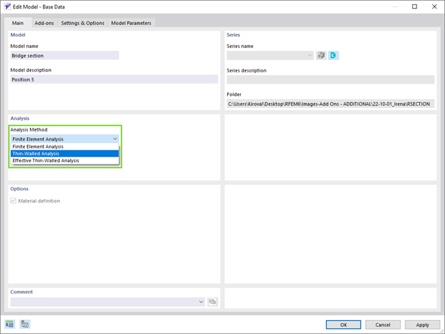
RSECTION contains an extensive library of rolled sections, as well as parametric thin-walled and massive cross-sections. You can compose them or supplement them with new elements.
Graphical tools and functions allow you to model complex section shapes in the usual way common for CAD programs. The graphical input supports, among other things, the setting of arcs, circles, ellipses, parabolas, and NURBS. As an alternative, you can import a DXF file and use this as the basis for further modeling. You can easily model a section consisting of different materials with minimum effort.
Furthermore, a parameterized input allows you to enter the cross-section dimensions and internal forces in such a way that they depend on certain variables.
You can also carry out all inputs by means of a script.

There are various tools, such as the object snap, user‑defined input grids, and guidelines, that facilitate the graphical input of structural data. Import DXF files as a line model in order to use specific snap points.
Work on your models with efficient and precise calculations in the digital wind tunnel. RWIND 2 uses a numerical CFD model (Computational Fluid Dynamics) to simulate wind flows around objects. Specific wind loads are generated from the simulation process for RFEM or RSTAB.
RWIND 2 performs this simulation using a 3D volume mesh. The program provides automatic meshing; you can easily set the entire mesh density as well as the local mesh refinement on the model using a few parameters. A numerical solver for incompressible turbulent flows is used to calculate the wind flows and the surface pressures on the model. The results are then extrapolated to your model. RWIND 2 is designed to work with different numerical solvers.
We currently recommend using the OpenFOAM® software package, which has provided very good results in our tests and is also a frequently used tool for CFD simulations. Alternative numerical solvers are under development.
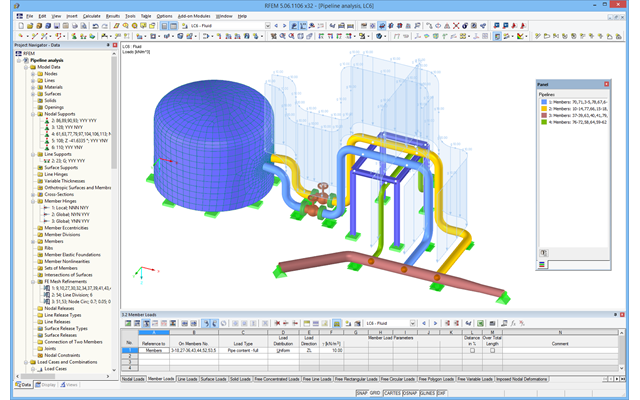
After activating the RF‑PIPING add‑on module, a new toolbar is available in RFEM and the project navigator and tables are extended. The piping system is now modeled in the same way as the members. Pipe bends are defined simultaneously by tangents (straight pipe sections) and radius. Thus, it is easy to subsequently change bend parameters.
It is also possible to extend the piping subsequently by defining special components (expansion joints, valves, and others). The implemented libraries of structural components facilitate the definition.
Continuous pipe sections are defined as sets of piping systems.
For piping loads, member loads are assigned to the respective load cases. The combination of loads is included in piping load combinations and result combinations.
After the calculation, you can display deformations, member internal forces, and support forces graphically or in tables.
Pipe stress analysis according to standards can then be performed in the RF‑PIPING Design add‑on module. You only need to select the relevant sets of piping systems and load situations.
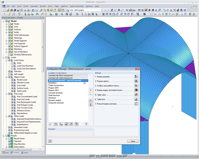
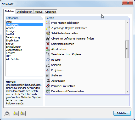
If you are interested in making your daily work easier and more efficient, you should also pay attention to this feature. Program configuration menus and toolbars can be freely customized. This allows you to arrange your frequently used functions in a user-defined way and save time. Everything from the beginning? No problem: You can restore the default settings of the program with a mouse click. Tables, navigators, and toolbars can also be moved and docked as required.
Furthermore, you can use the configuration manager to set the graphic display properties, toolbars, and so on in a user-defined way and save them as your own configuration. Thus, the software becomes your individual productivity enhancer.
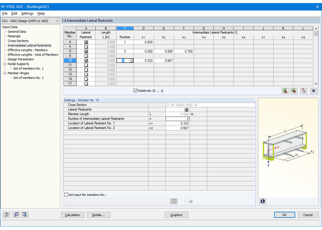
First, it is necessary to decide whether to perform design according to ASD or LRFD. Then, you can enter the load cases, load combinations, and result combinations to be designed. Load combinations according to ASCE 7 can be generated either manually or automatically in RFEM/RSTAB.
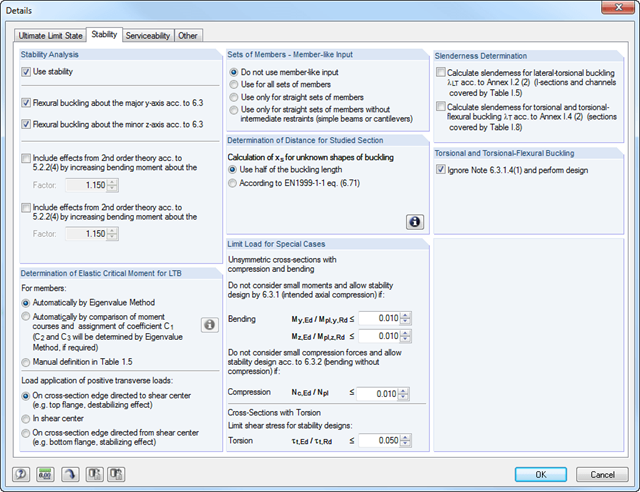
In the next steps, you can adjust presettings of lateral intermediate supports, effective lengths, and other standard-specific design parameters, such as the modification factor Cb for lateral-torsional buckling or the shear lag factor. In the case of continuous members, it is possible to define individual support conditions and eccentricities of each intermediate node of single members. A special FEA tool determines critical loads and moments required for the stability analysis.
In connection with RFEM/RSTAB, it is possible to apply the Direct Analysis Method taking into account the influence of the general calculation according to the second-order analysis. In this way, you avoid using special enlargement factors.
First, it is necessary to decide whether to perform design according to ASD or LRFD. Then, you can enter the load cases, load combinations, and result combinations to be designed. Load combinations according to ASCE 7 can be generated either manually or automatically in RFEM/RSTAB.
Further specifications include presetting of lateral intermediate supports, effective lengths, and other standard-specific design parameters. When using continuous members, it is possible to define individual support conditions and eccentricities at each intermediate node of the single members. A special FEA tool then internally determines the effective radii of gyration required for the stability analysis for these situations.

SHAPE-THIN includes an extensive library of rolled and parameterized cross-sections. They can be composed or supplemented by new elements. It is possible to model a section consisting of different materials.
Graphical tools and functions allow for modeling complex section shapes in the usual way common for CAD programs. The graphical entry provides the option of setting point elements, fillet welds, arcs, parameterized rectangular and circular sections, ellipses, elliptical arcs, parabolas, hyperbolas, spline, and NURBS. Alternatively, it is possible to import a DXF file that is used as the basis for further modeling. You can also use guidelines for modeling.
Furthermore, parameterized input allows you to enter model and load data in a specific way so they depend on certain variables.
Elements can be divided or attached to other objects graphically. SHAPE-THIN automatically divides the elements and provides for an uninterrupted shear flow by introducing dummy elements. In the case of dummy elements, you can define a specific thickness to control the shear transfer.
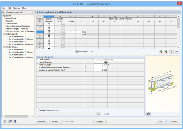
It is necessary to enter material, load, and combination data in RFEM/RSTAB in compliance with the design concept specified by the Code of Practice for the Structural Use of Steel 2011 (Buildings Department – Hong Kong).
The RF-/STEEL HK add-on module requires members and sets of members as well as load cases, load combinations, and result combinations to be designed. In the subsequent input windows, you can adjust preset definitions of lateral intermediate supports and effective lengths.
In the case of continuous members, it is possible to define individual support conditions and eccentricities of each intermediate node of single members. A special FEA tool then determines the critical loads and moments required for the stability analysis in these situations.
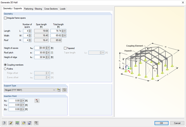
Generating tools to enter parametric models such as frames, halls, trusses, spiral stairways, arcs, or roofs. In addition, many generators allow for the creation of load cases and loading resulting from weight, snow, and wind.
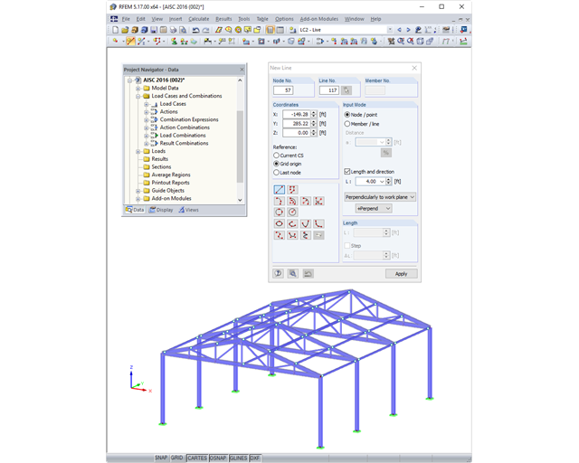
There are various tools such as the object snap, user‑defined input grids, and guidelines, that facilitate the graphical input of structural data. DXF files can be imported as line models or used as a layer in the background in order to use specific snap points.
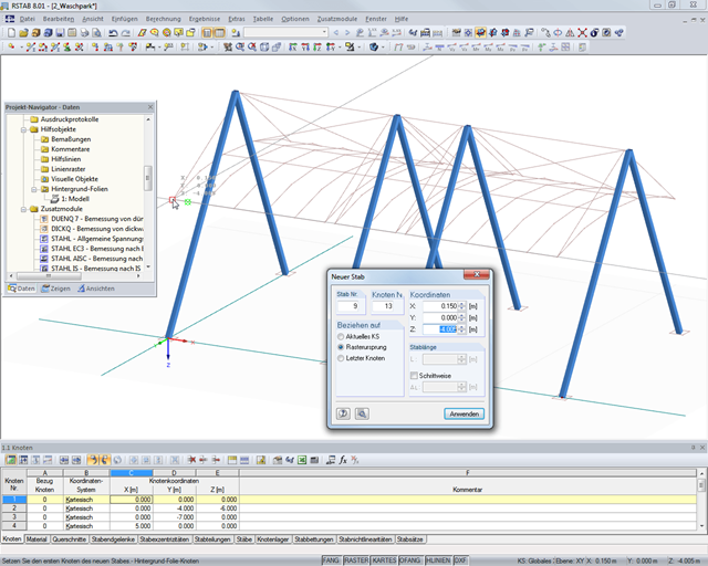
There are various tools such as the object snap, user‑defined input grids, and guidelines, that facilitate the graphical input of structural data. DXF files can be imported as line models or used as a layer in the background in order to use specific snap points.
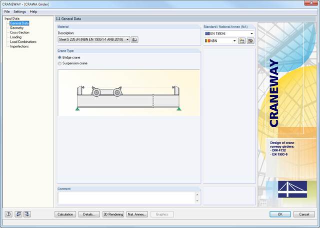
Geometry, material, cross-section, action, and imperfection data are entered in clearly arranged input windows:
Geometry
- Quick and convenient data input
- Definition of support conditions based on various support types (hinged, hinged movable, rigid, and user-defined, as well as lateral on upper or bottom flange)
- Optional specification of warping restraint
- Variable arrangement of rigid and deformable support stiffeners
- Possibility to insert hinges
CRANEWAY Cross-Sections
- I-shaped rolled cross-sections (I, IPE, IPEa, IPEo, IPEv, HE-B, HE-A, HE-AA, HL, HE-M, HE, HD, HP, IPB-S, IPB-SB, W, UB, UC, and other cross-sections according to AISC, ARBED, British Steel, Gost, TU, JIS, YB, GB, and others) combinable with section stiffener on the upper flange (angles or channels) as well as rail (SA, SF) or splice with user-defined dimensions
- Unsymmetrical I-sections (type IU) also combinable with stiffeners on the upper flange as well as with rail or splice
Actions
It is possible to consider the actions of up to three simultaneously operated cranes. You can simply select a standard crane from the library. You can also enter data manually:
- Number of cranes and crane axles (maximum of 20 axles per crane), center distances, position of crane buffers
- Classification in damage classes with editable dynamic factors according to EN 1993-6, and in lifting classes and exposure categories according to DIN 4132
- Vertical and horizontal wheel loads from self-weight, hoist load, mass forces from drive, as well as loads from skewing
- Axial loading in driving direction as well as buffer forces with user-defined eccentricities
- Permanent and variable secondary loads with user-defined eccentricities
Imperfections
- The imperfection load applies in compliance with the first natural vibration mode - either identically for all load combinations to be designed, or individually for each load combination, as mode shapes may vary depending on the load.
- Convenient tools available for scaling the mode shapes (rise determination of inclination and precamber).
.png?mw=640&hash=53c64389797699e939283ddbfc3d88485fcbfbf5)
- Full integration in RFEM/RSTAB, including import of all relevant loads
- General stress analysis with warping torsion according to elastic-elastic method
- Stability analysis of planar continuous members for buckling and lateral-torsional buckling
- Determination of critical load factor and thus of Mcr or Ncr (the factor can be used in RF-/LTB for the el/pl design)
- Lateral-torsional buckling analysis of any cross-section (also the SHAPE-THIN cross-sections)
- Design of members and sets of members with applied torsion (for example, crane girder)
- Optional determination of the limit load factor (critical load factor)
- Display of eigenmodes and torsional modes on the rendered cross-section
- Wide range of tools for determining shear panels and rotational restraints (such as corrugated sheets, purlins, bracings)
- Easy determination of discrete springs such as warp springs from end plates or rotational springs from columns
- Graphical selection of load application points on a cross-section (upper chord, centroid, lower chord, or any other point)
- Free arrangement of eccentric nodal and line supports on a cross-section
- Determination of value for inclination or precamber by means of eigenvalue analysis
- Special warping releases applicable for definition of warping conditions on transitions
The data specified in RFEM/RSTAB concerning material, loads, and load combinations must comply with the design concept of the Eurocode. The RFEM/RSTAB material library already contains the relevant materials. Furthermore, RFEM/RSTAB allows for automatic creation of load and result combinations in accordance with the Eurocode. It is also possible to create the combinations manually.
In the RF-/ALUMINUM add-on module, you must first select the members and sets of members to be designed, as well as the load cases, load combinations, and result combinations. In the subsequent input windows, you can adjust preset definitions of lateral intermediate supports and effective lengths.
When using continuous members, you can define individual support conditions and eccentricities for each intermediate node of the single members. A special FEA tool determines the critical loads and moments required for the stability analysis.
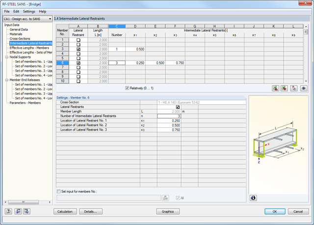
It is necessary to enter material, load, and combination data in RFEM/RSTAB in compliance with the design concept specified by the standard SANS 10162-1:2011. The RFEM/RSTAB material library already contains materials relevant for the South African standard.
The RF-/STEEL SANS add-on module requires members and sets of members as well as load cases, load combinations, and result combinations to be designed. In the subsequent input windows, you can adjust preset definitions of lateral intermediate supports and effective lengths.
In the case of continuous members, it is possible to define individual support conditions and eccentricities of each intermediate node of single members. A special FEA tool then determines the critical loads and moments required for the stability analysis in these situations.
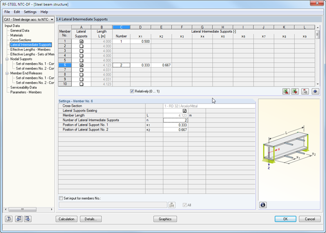
First, you have to select the load cases, load combinations, and result combinations to be designed. It is also necessary to enter material, load, and combination data in RFEM/RSTAB in compliance with the design concept specified by the standard NTC-RCDF (2004). The RFEM/RSTAB material library already contains materials relevant for the Mexican and American standards.
Further specifications include presetting of lateral intermediate supports, effective lengths, and other standard-specific design parameters. In the case of continuous members, it is possible to define individual support conditions and eccentricities of each intermediate node of single members. A special FEA tool then determines the critical loads and moments required for the stability analysis in these situations.
In connection with RFEM/RSTAB, it is possible to consider the effect of the general calculation according to the second-order analysis by default. Alternatively, you can create the second-order analysis effects by using enlargement factors.
First, you have to select the load cases, load combinations, and result combinations to be designed.
Further specifications include presetting of lateral intermediate supports, effective lengths, and other standard-specific design parameters. In the case of continuous members, it is possible to define individual support conditions and eccentricities of each intermediate node of single members. A special FEA tool then determines the critical loads and moments required for the stability analysis in these situations.
In connection with RFEM/RSTAB, it is possible to apply the Direct Analysis Method taking into account the influence of the general calculation according to the second-order analysis. In this way, you avoid using special enlargement factors.
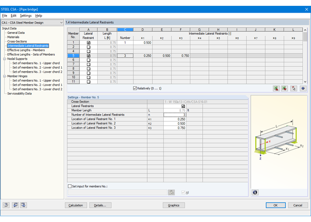
It is necessary to enter material, load, and combination data in RFEM/RSTAB in compliance with the design concept specified by CSA S16. The RFEM/RSTAB material library already contains materials relevant for the Canadian standard.
RFEM/RSTAB automatically creates the corresponding load combinations according to the Canadian standard. However, you can also create all the combinations manually in RFEM/RSTAB. The RF-/STEEL CSA add-on module requires members and sets of members, as well as load cases, load combinations, and result combinations to be designed.
In the subsequent input windows, you can adjust preset definitions of lateral intermediate supports and effective lengths. In the case of continuous members, it is possible to define individual support conditions and eccentricities of each intermediate node of single members. A special FEA tool then determines the critical loads and moments required for the stability analysis in these situations.
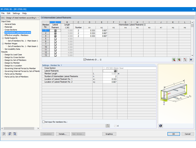
It is necessary to enter material, load, and combination data in RFEM/RSTAB in compliance with the design concept specified by BS 5950 (or Eurocode). The RFEM/RSTAB material library already contains relevant materials for BS 5950.
RFEM/RSTAB automatically creates the corresponding load combinations according to BS 5950 (or Eurocode). However, you can also create all the combinations manually in RFEM/RSTAB. The RF-/STEEL BS add-on module requires members and sets of members, as well as load cases, load combinations, and result combinations to be designed.
In the subsequent input windows, you can adjust preset definitions of lateral intermediate supports and effective lengths. In the case of continuous members, it is possible to define individual support conditions and eccentricities of each intermediate node of single members. A special FEA tool then determines the critical loads and moments required for the stability analysis in these situations.
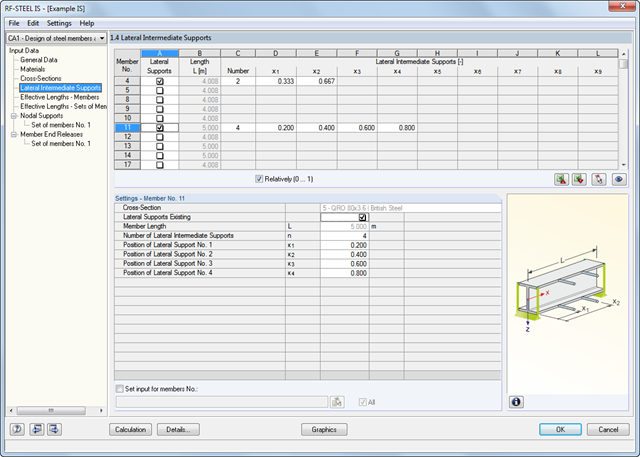
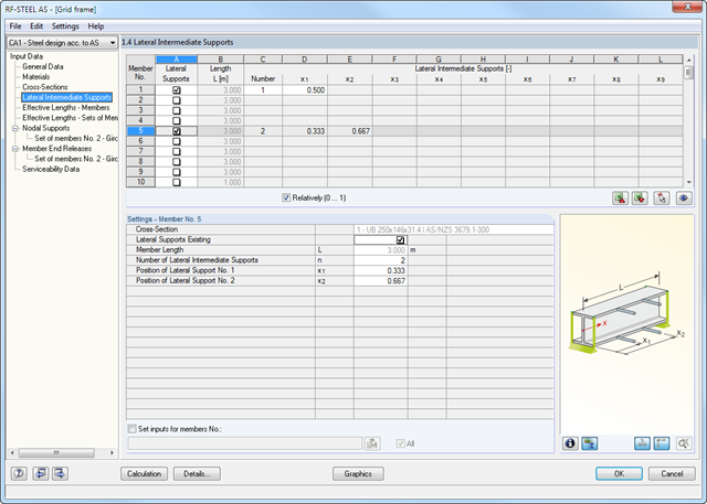
It is necessary to enter material, load, and combination data in RFEM/RSTAB in compliance with the design concept specified by IS 800. The RFEM/RSTAB material library already contains relevant materials for IS 800.
RFEM/RSTAB automatically creates the corresponding load combinations according to IS 800. However, you can also create all the combinations manually in RFEM/RSTAB. The RF-/STEEL IS add-on module requires members and sets of members as well as load cases, load combinations, and result combinations to be designed.
In the subsequent input windows, you can adjust preset definitions of lateral intermediate supports and effective lengths. In the case of continuous members, it is possible to define individual support conditions and eccentricities of each intermediate node of single members. A special FEA tool determines critical loads and moments required for the stability analysis.
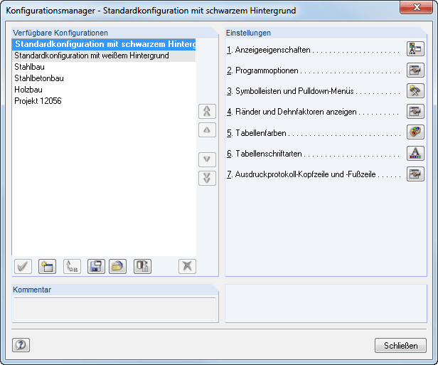
The Configuration Manager provides the option to specify user‑defined settings of display properties, program options, toolbars, and others, which can be saved as separate configurations. It is possible to save several configurations.
Program configuration menus and toolbars can be freely customized. It is possible to setup an arrangement of frequently used functions and tools for quick access. Tables, navigators, and toolbars can also be freely moved and docked. The default settings of the program can be restored at the click of a button.
In addition, it is possible in the Configuration Manager to set the graphic display properties, toolbars, and so on in a user-defined way and save them as your own configuration.
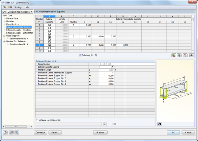
It is necessary to enter material, load, and combination data in RFEM/RSTAB in compliance with the design concept specified by SIA 263.
The RFEM/RSTAB material library already contains the relevant materials for SIA. Furthermore, RFEM/RSTAB automatically creates the corresponding load combinations according to SIA 260. However, you can also create all the combinations manually in RFEM/RSTAB.
The RF-/STEEL SIA add-on module requires members and sets of members, as well as load cases, load combinations, and result combinations to be designed. In the next steps, you can adjust the preset definitions of lateral intermediate supports and effective lengths.
In the case of continuous members, it is possible to define individual support conditions and eccentricities of each intermediate node of single members. A special FEA tool then determines the critical loads and moments required for the stability analysis in these situations.